
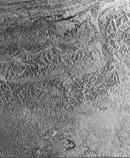
Pine Mountain Radar Image
In many radar images where the terrain is quite mountainous with high relief, unusual geometric effects may appear. Radar-blocked shadows become wider as look angles increase. Hill or ridge slopes facing the radar appear distorted, which we call foreshortening, expressed as a compressing or "thinning" of slopes on the facing (bright- toned) side and an elongating on the shadowed side. The next image displays this effect well. It’s a Seasat image of part of the Pine Mountain thrust in North Carolina:
 |
Seasat Image of Pine Mountain thrust |
The look direction, along which the radar beam is traveling, can always be determined by the position of bright slopes - like those that are sunlit indicating where the Sun is azimuthally, the radar platform will be to the right (looking in the opposite direction) at approximately 90° to the pattern of elongated bright slopes. Radar-blocked shadows become wider as look angles increase.
Hill or ridge slopes facing the radar are subject to a distorted appearance called foreshortening expressed as a compresion or "thinning" of slopes on the facing (bright- toned) side and an elongation on the side that is shadowed. All foreslopes (those facing the incoming beam, here from the right side) are shortened to some extent in radar images. Visually, these slopes appear distorted, with the facing slopes seeming to lean toward the radar platform, as though they are steeper. As depression angles increase, the geometry makes the slope lengths (top to bottom) appear to progressively decrease, thus increasing the degree of foreshortening.
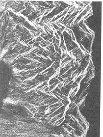
This slope displacement is more pronounced in the near range part of a scene than in the far. Geometrically, foreshortening occurs wherever the radar wavefront is steeper than the slope angles illuminated by the beam. In the extreme, slopes appear as though inverted and laid over, which we call layover. This effect occurs when the look angle is less than the foreslope angle, causing the top of a slope to send its returns before the bottom does (the distortion is worst in near-range locations). An example of this in mountainous terrain appears on the left.
8-11: From what direction is the incoming radar illumination coming? Describe the physical appearance of the mountains, i.e., characterize the distortion. ANSWER
Slant range images may also show another geometric contortion, expressed as compression of regularly shaped features (square crop fields may look similar to a rhombus), being maximum at near-range positions in flat terrain. We can convert these images to ground range images if we know independent information on topography. Still other distortions come from erratic aircraft motions during flight (which are nil from stable space platforms). We can also compensate for these by further processing.
Effect of Illumination Angles
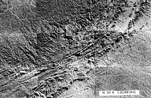
Linear features in rolling or mountainous terrains, such as long, straight valleys or ridge crests, may stand out with a combination of bright slope-shadow effects, in which the patterns change depending on their orientations relative to the flight line or look direction. We illustrate this effect with an interesting analog experiment conducted by Professor Donald Wise (University of Massachusetts), using a three-dimensional topographic map that was illuminated at low artificial light angles from several directions:
 |
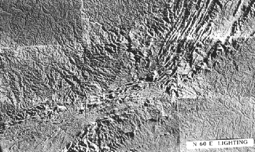 |
A simple glance at the two images shows an immediately obvious difference: ridges and valleys that trend N 30° E are strongly enhanced in the N 60° E image, whereas similar features illuminated from the N 30° E direction are emphasized if their linear orientations trend N 60° E. Note, in both cases the sum of the two angles is 90°; in other words, illumination is perpendicular to the trend that stands out. Other features at varying orientations are visible in each scene but with subdued expression. As we saw in Section 2, this phenomenon - that linear trends are greatly influenced by illumination azimuth and angle - is quite pronounced in Landsat images, producing a directional bias. That bias is evident from the plots of fractures on azimuthal rose diagrams, where those oriented northeast-southwest (roughly perpendicular to mid-morning sun angles) tend to dominate the distribution of orientations. This trend can be an advantage in airborne radar imagery, because we can chose flight line directions to underscore and accentuate certain directions of interest to optimize detection of fractures in all orientations.
This dependency on direction of illumination is used to good advantage in conducting radar flights over terrains that are sensitive to differences in orientation of mountain ridges, fault valleys, and other conditions where linear features are being sought. Consider this image of Precambrian rocks in the African nation of Nigeria.
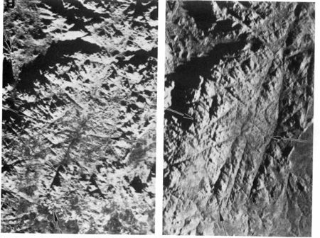
In the left image, the look direction is from the bottom; in the right image illumination is from the right. Same scene - but with notable differences in the expression of topography and structural features.
8-12: Comment on several of the more obvious differences? ANSWER

Collaborators: Code 935 NASA GSFC, GST, USAF Academy
Contributor Information
Last Updated: September '99
Webmaster: Bill Dickinson Jr.
Site Curator: Nannette Fekete
Please direct any comments to rstweb@gst.com.