
We have already shown several previews of imagery that depict the thermal state of the Earth's surface. The Landsat Thematic Mapper band 6 produces images that show the relative differences in emitted thermal energy from surfaces of varying nature and orientation. In Section 1, we showed this effect in the obviously warmer slopes in the Morro Bay scene and the surprisingly cool surfaces of the bright, white sandstone at the Waterpocket Fold. In seeming contradiction, the warmer surfaces associated with dark shales showed clearly in the Waterpocket Fold image. As we shall show, these thermal effects also differ, sometimes drastically, in images taken during the warmer days and cooler nights. We usually obtain considerable information from thermal imagery, especially that obtained from multispectral images. Some of this information supplements images obtained from reflected radiation and some stands alone as an information source. In this section review, we delve rather extensively into the theory and practice of thermal remote sensing and examine some striking examples obtained from land and water targets. However, we postpone our discussion of using thermal sensors to obtain temperature profiles or find other thermal properties in the atmosphere until we consider meteorological satellites (Section 14).
We perform remote sensing of direct temperature effects by sensing radiation emitted from matter in the thermal infrared region of the spectrum. Thermal sensing of solids and liquids occurs in two atmospheric windows, where absorption is a minimum, as shown in this spectral plot taken from Sabins (Remote Sensing: Principles and Interpretation, 1987).
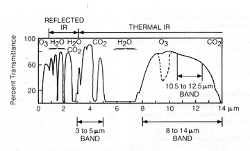
The windows normally used from aircraft platforms are in the 3-5 mm and 8-14 µm wavelength regions. Space borne sensors commonly use windows between 3 and 4 µm and between 10.5-12.5 µm. None of the windows transmits 100 percent because water vapor and carbon dioxide absorb some of the energy across the spectrum and ozone absorbs energy in the 10.5-12.5 µm interval. In addition, solar reflectance contaminates the 3-4 µm window to some degree during daylight hours, so we use it for Earth studies only when measurements are made at night.
Planck Blackbody Law
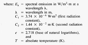
Two material properties determine the amount of thermal radiation emitted by an object: internal temperature and emissivity. The Planck Blackbody Law gives the rate at which objects radiate energy:
E![]() = C1
= C1![]() -5[exp (C2/
-5[exp (C2/![]() T) - 1]-1,
T) - 1]-1,
A perfect blackbody is the concept of an ideal material that completely absorbs all incident radiation, converting it to internal energy. Therefore it does not permit any transmittance or reflectance but emits the absorbed energy at the maximum possible rate.

Collaborators: Code 935 NASA GSFC, GST, USAF Academy
Contributor Information
Last Updated: September '99
Webmaster: Bill Dickinson Jr.
Site Curator: Nannette Fekete
Please direct any comments to rstweb@gst.com.